Composite Tooling for MotoAmerica Carbon Fiber Race Fairings
Additively Manufactured Mold Development Under Two-Week Timeline.
Composite Tooling for MotoAmerica Carbon Fiber Race Fairings
Overview
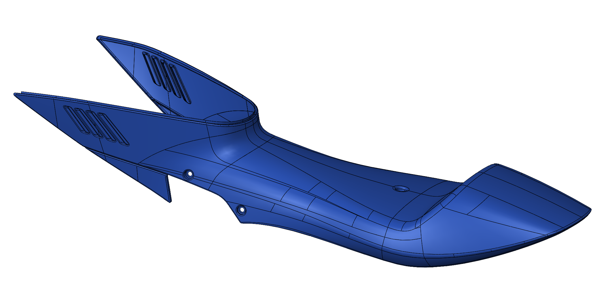
A MotoAmerica race team required composite tooling for carbon fiber fairings within a compressed two week race preparation window. The team provided aerodynamic surface models representing the final fairing geometry, but these surfaces were not mold ready and had not been developed with additive manufacturing or hand layup constraints in mind.
The objective was clear. Translate digital fairing surfaces into manufacturable composite tooling quickly and reliably without compromising dimensional accuracy or composite quality.
The Challenge
The schedule left little room for traditional tooling methods. Additive manufacturing was selected as the fastest viable path to mold production, but the geometry still required careful engineering to ensure reliable layup and release.
The mold design required:
Integration of draft angles, parting strategy, and release geometry
A multi part assembly strategy compatible with available print volume
Dimensional fidelity maintained through bonding and surface finishing
Thermal stability during epoxy cure
Delivery within a two week race preparation timeline
Surface continuity after bonding was treated as a primary constraint. Any distortion introduced during segmentation or assembly would transfer directly into the final composite fairing.
Process
1. Clarify Objectives and Constraints
Initial discussions with the race engineer focused on performance requirements, dimensional tolerances, and the two week production timeline. Manufacturing constraints were reviewed to determine available print volume and segmentation strategy.
The objective was to develop mold geometry that could be fabricated rapidly while preserving composite quality.
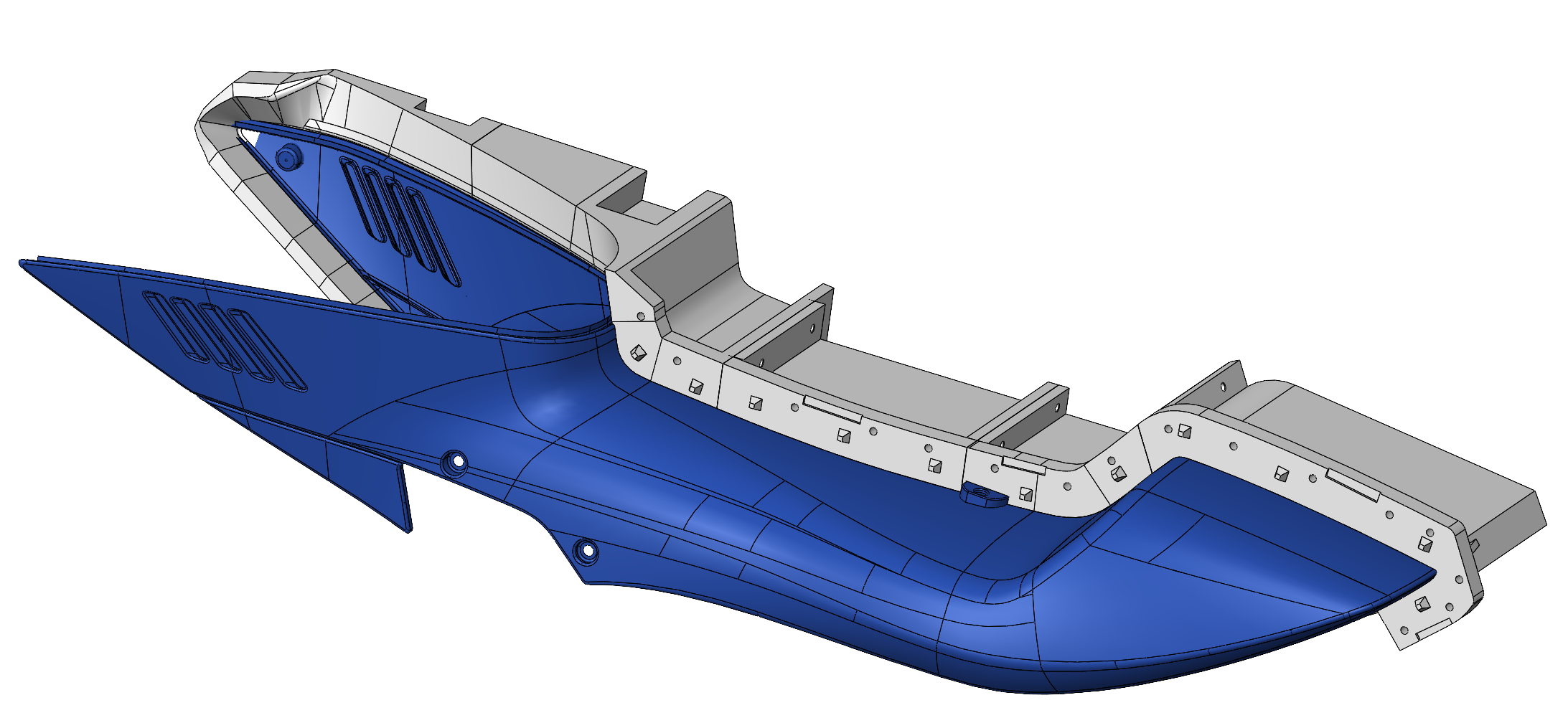
2. Convert Surface Models to Manufacturable Mold Geometry
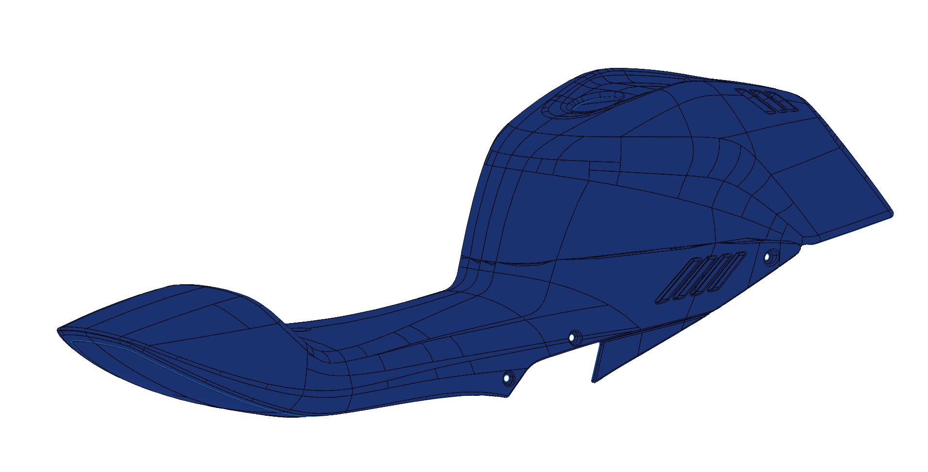
The provided aerodynamic surfaces were converted into mold ready geometry and engineered specifically for additive manufacturing and hand layup.
Tooling development incorporated:
Draft angles and parting strategy for clean release
Bonding interfaces between segmented sections
Print orientation considerations for strength and dimensional stability
Alignment features to preserve surface continuity after assembly
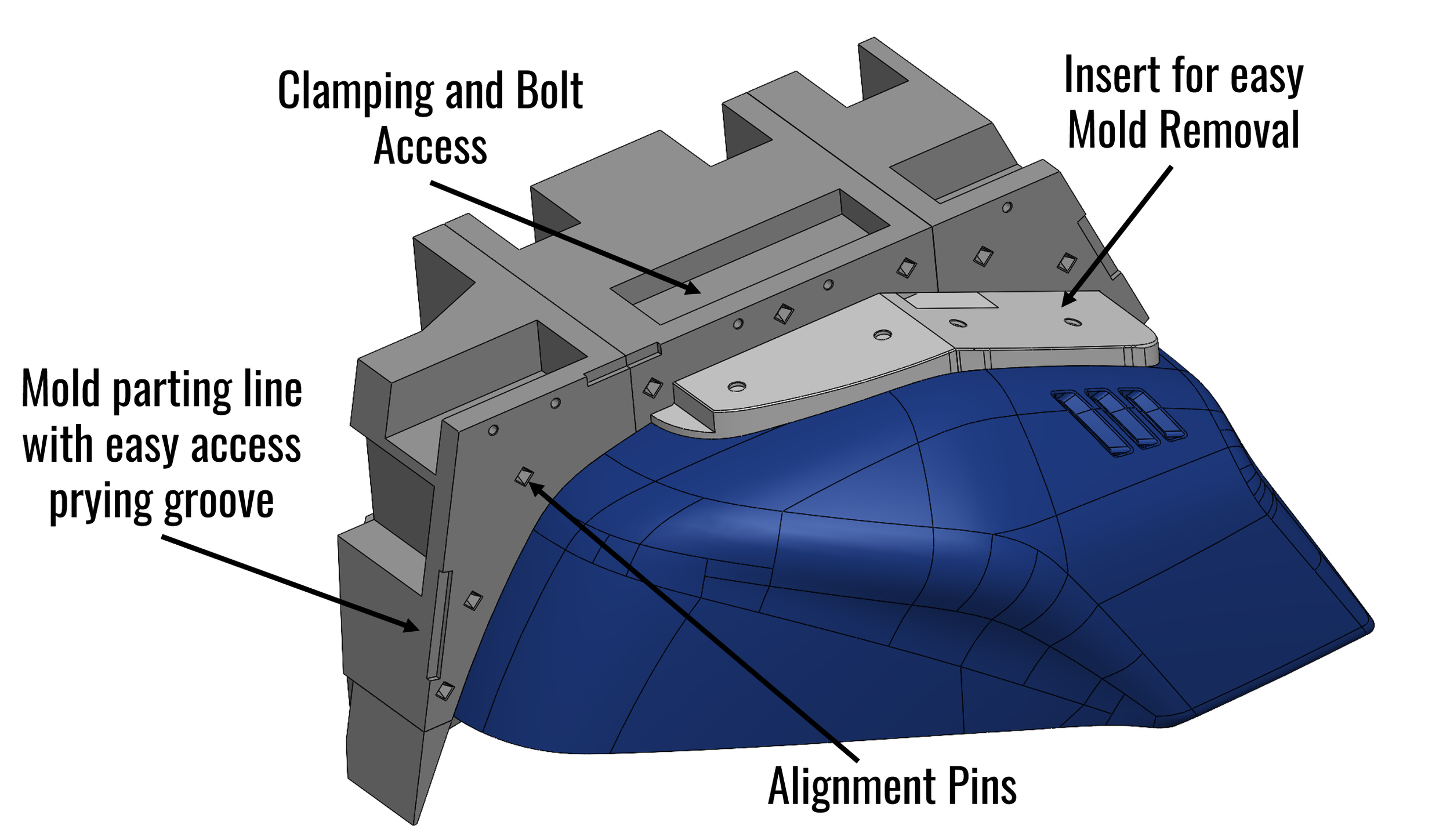
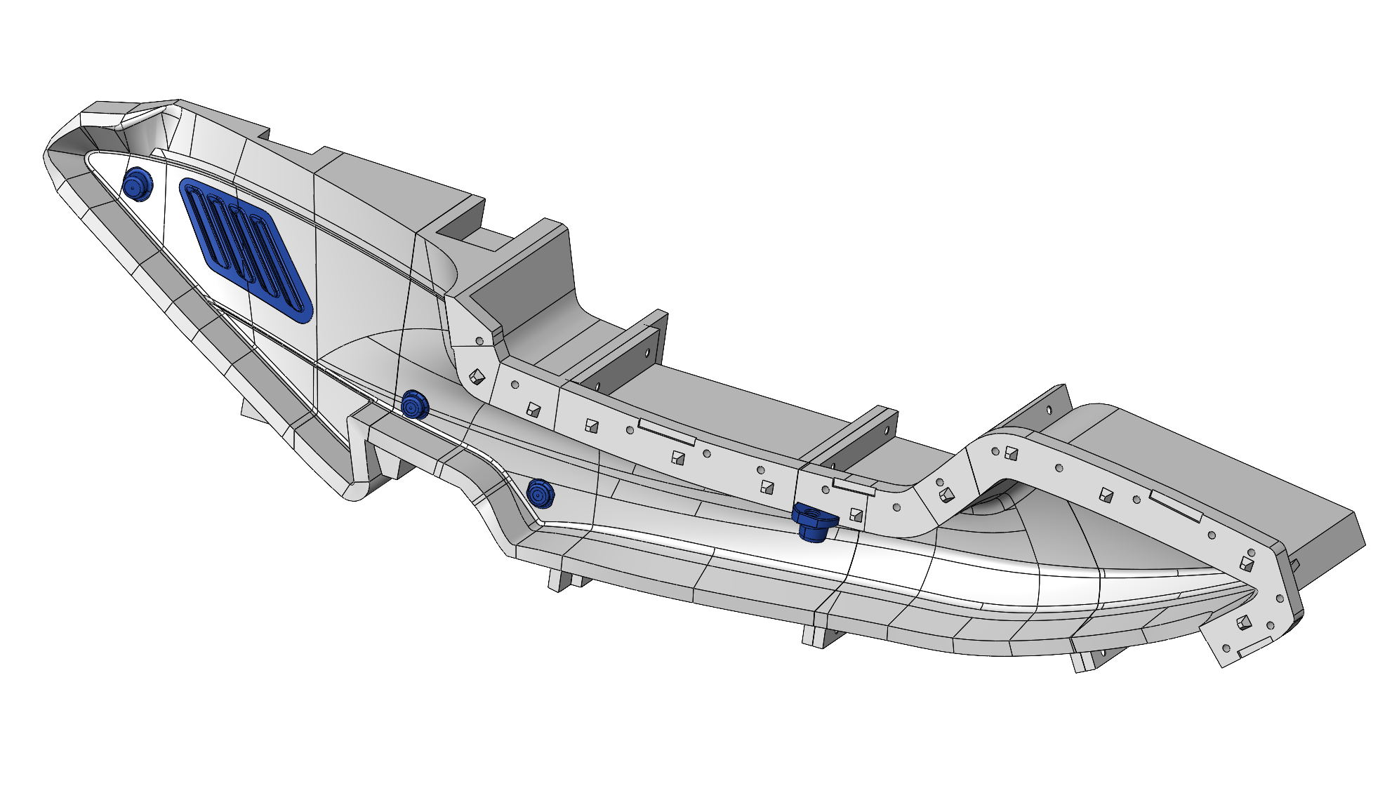
Because the molds were additively manufactured, additional features were integrated directly into the geometry to improve assembly accuracy and composite handling.
These included:
Integrated alignment pins to control surface continuity across bonded sections
A defined mold parting line with accessible prying groove for controlled separation
Integrated clamping and bolt access geometry to support secure layup
Alignment features to preserve surface continuity after assembly
3. Plan for Assembly and Composite Execution
Assembly sequencing, bonding strategy, and surface finishing approach were defined to maintain dimensional continuity after segmentation.
Demolding strategy was coordinated with a composite specialist to ensure controlled release in complex geometry regions.
This preparation allowed the tooling to move directly into composite layup without geometry revision.
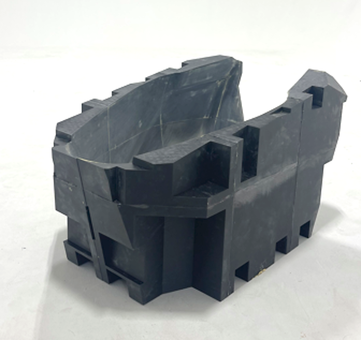
Additive Tooling Strategy
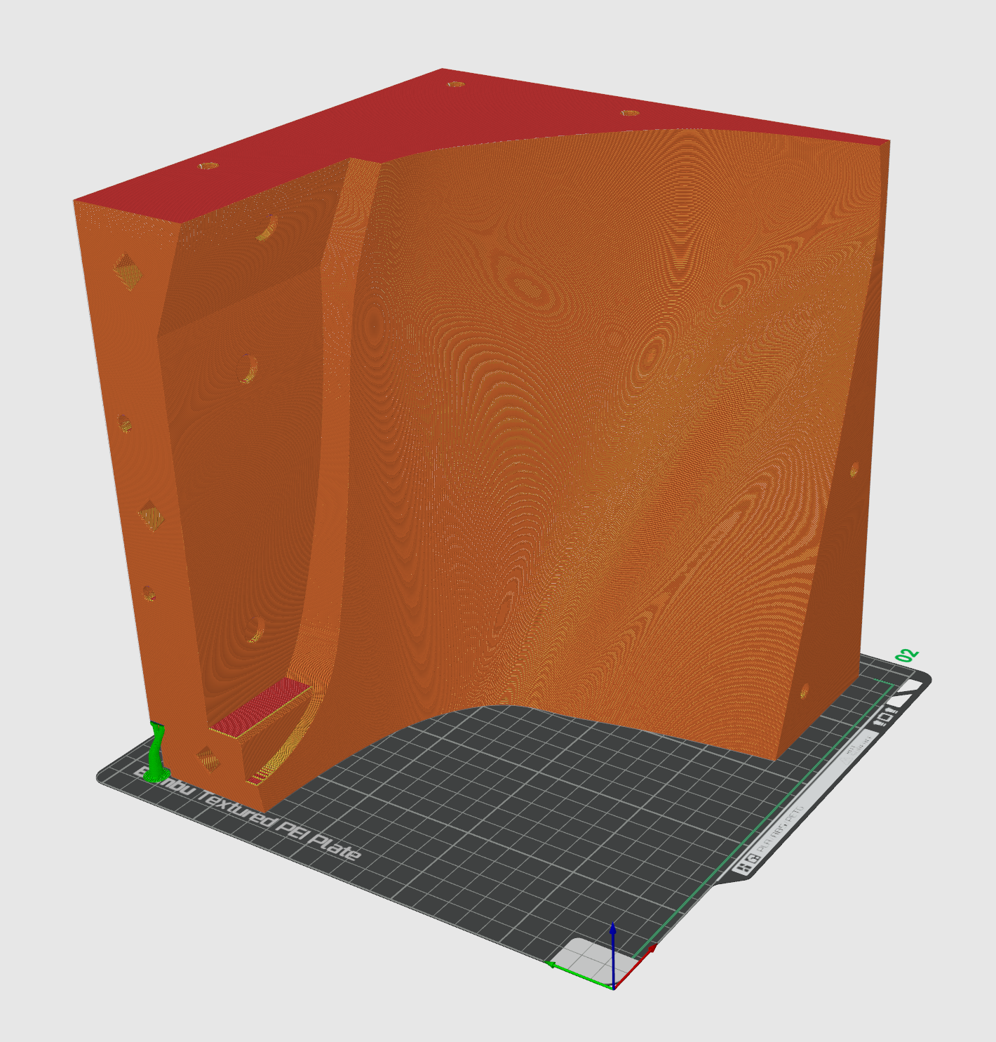
The molds were produced using PET G to provide thermal stability during epoxy cure while enabling rapid fabrication on desktop scale additive equipment.
Given the two week schedule, the molds were intentionally designed for single use. The strategy prioritized fast production and reliable geometry over extended service life.
Tooling components were distributed across coordinated build platforms to meet schedule demands. Print layout and orientation were planned to balance throughput, dimensional stability, and assembly accuracy.
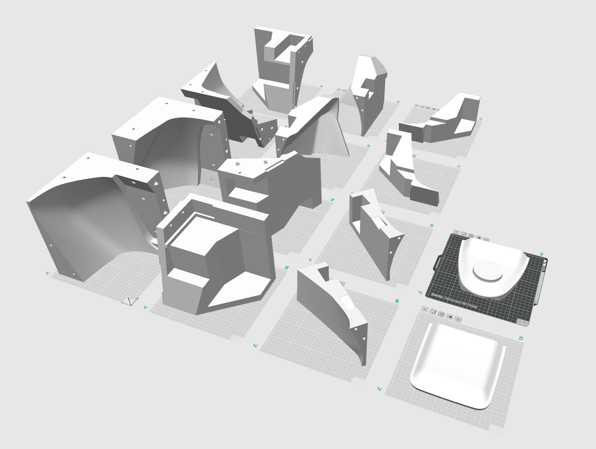
Outcome
The segmented PET G mold components were printed, bonded, and surface finished to achieve the required surface continuity and dimensional fidelity.
The assembled tooling supported composite fabrication within the two week schedule, enabling the team to proceed directly into layup and race preparation without geometry revision or tooling rework.
Final Application
The completed fairings were installed and used in race preparation.
Engineering Takeaways
Early segmentation decisions directly affect assembly accuracy and finishing effort.
Tooling geometry should integrate alignment and clamping strategy rather than treating them as secondary features.
Print layout and orientation must be coordinated with assembly requirements, not just printer constraints.
Tooling material selection should be driven by process conditions, not convenience.
When schedule is the dominant constraint, intentional single use tooling can be the correct strategic choice.
.
Applying This Approach
Whether developing composite tooling, transitioning a concept into production, or evaluating additive as part of a manufacturing strategy, the same principles apply:
Clarify constraints early.
Engineer geometry for fabrication.
Plan assembly and execution intentionally.
Select materials and processes based on real use conditions.
If you are developing a product, tooling system, or custom fabrication project and need support translating design intent into manufacturable reality, I’d be glad to discuss your application.