Magnet Fan System Development
Modular Magnetic Ventilation System for Rooftop Tents
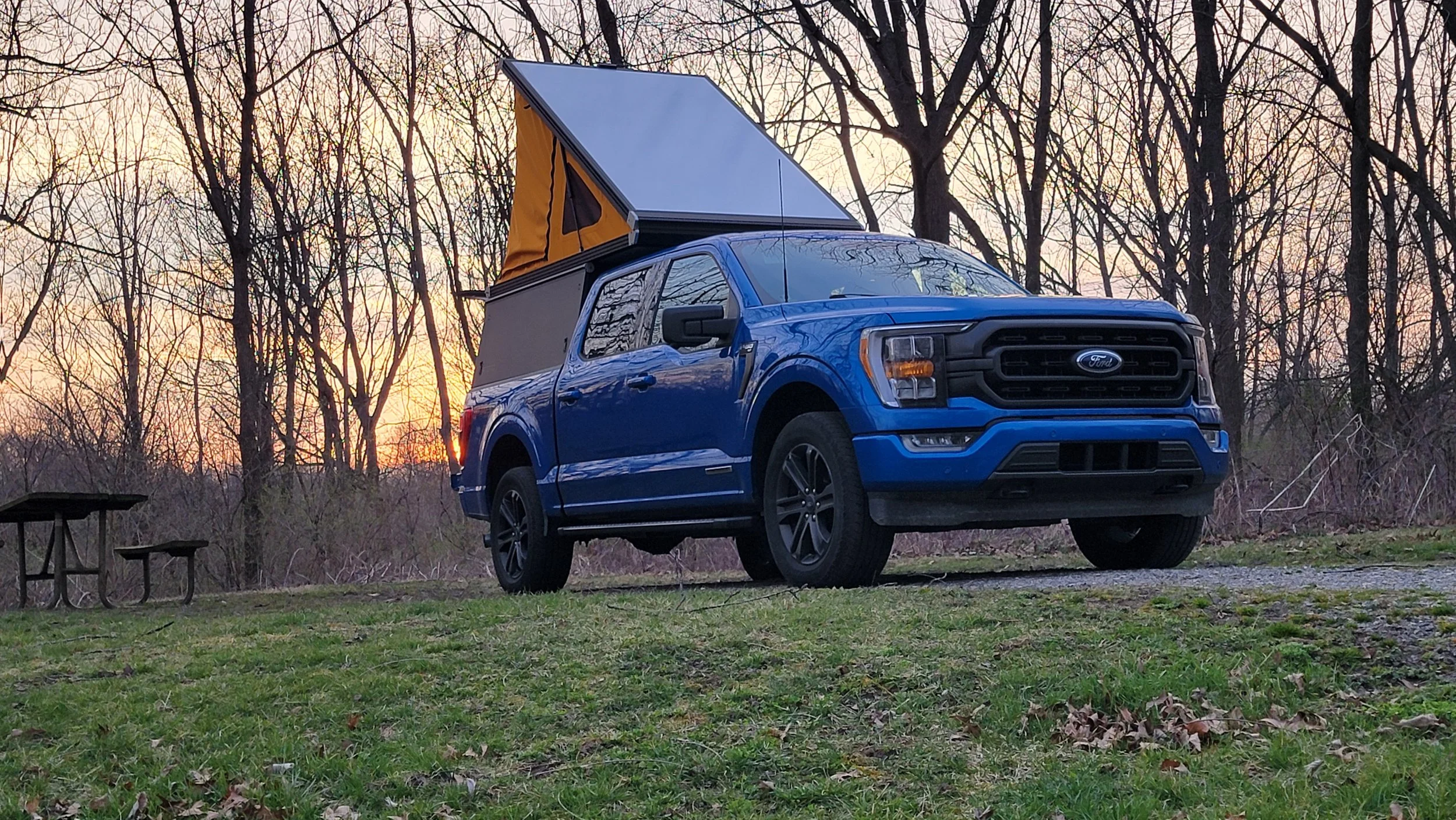
After spending summer nights in a rooftop tent with stagnant air, I set out to develop a compact, quiet ventilation solution that mounted cleanly without permanent modification.
What started as a personal need became a structured product development exercise — moving from proof of concept through system refinement and into small-batch production.
This project demonstrates how thoughtful design, additive manufacturing, and disciplined iteration can turn a simple idea into a reliable product.
Overview
Core Requirements
From the beginning, several requirements were equally important:
Durable and mechanically reliable
Effective airflow in a confined space
Lightweight and easy to mount
Adjustable speed control
Quiet enough for sleeping
Powered by USB-C
Balancing these constraints required tradeoffs rather than optimizing a single feature.
Development Process
1. Component Selection and Early Testing
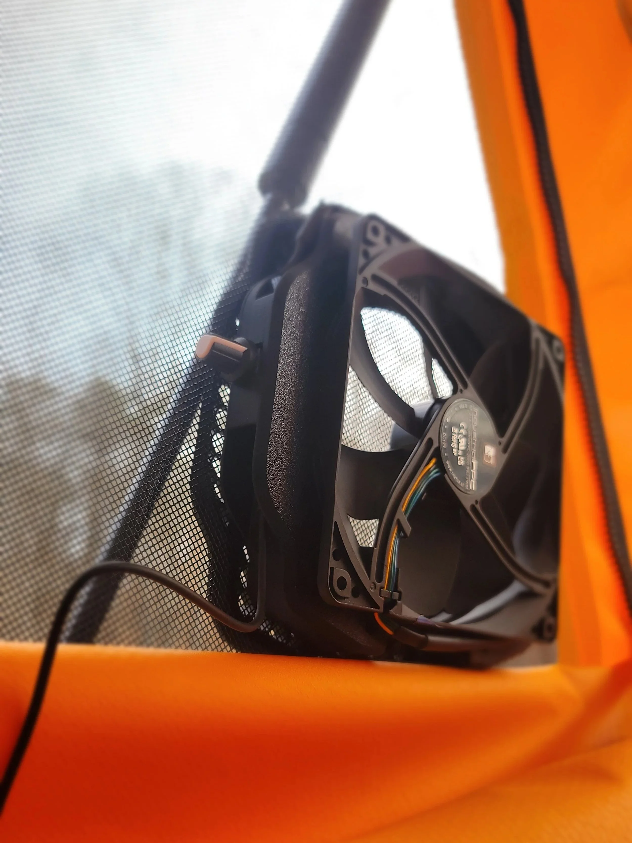
To evaluate airflow and packaging constraints, two fan sizes from the same manufacturer were tested: a 220mm model and a 140mm model.
The larger fan offered increased airflow but introduced challenges in packaging, print size, weight, and cost. The smaller, faster 140mm model provided sufficient airflow while improving printability, reducing material usage, and lowering overall system cost.
This comparative testing phase informed the final system architecture before housing development began.
An early magnetic mounting prototype validated:
Airflow effectiveness inside the tent
Noise level during sleep
Mounting stability
Overall usability
This comparative testing phase reduced risk before committing to full housing development.
220mm Model140 mm Model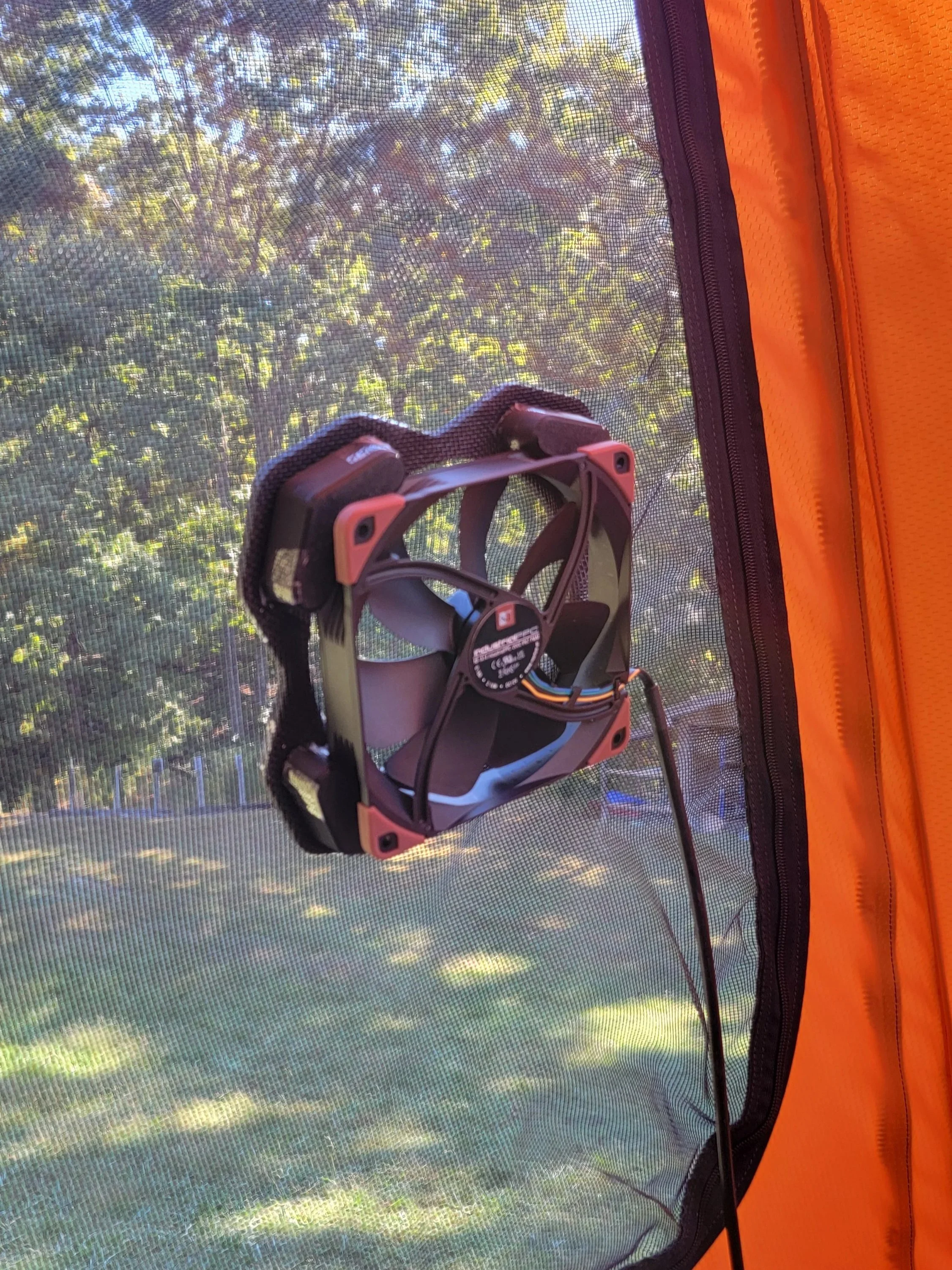
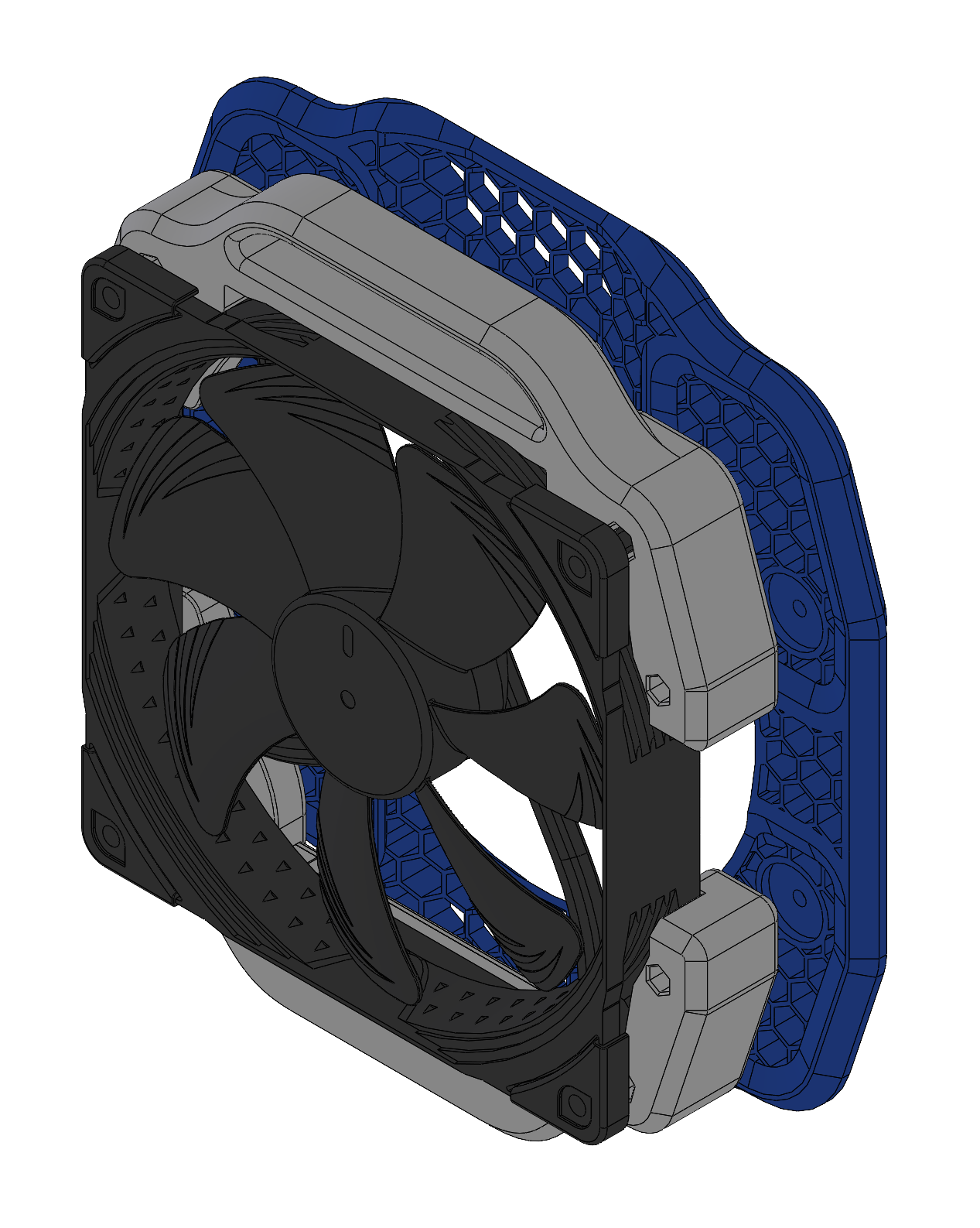
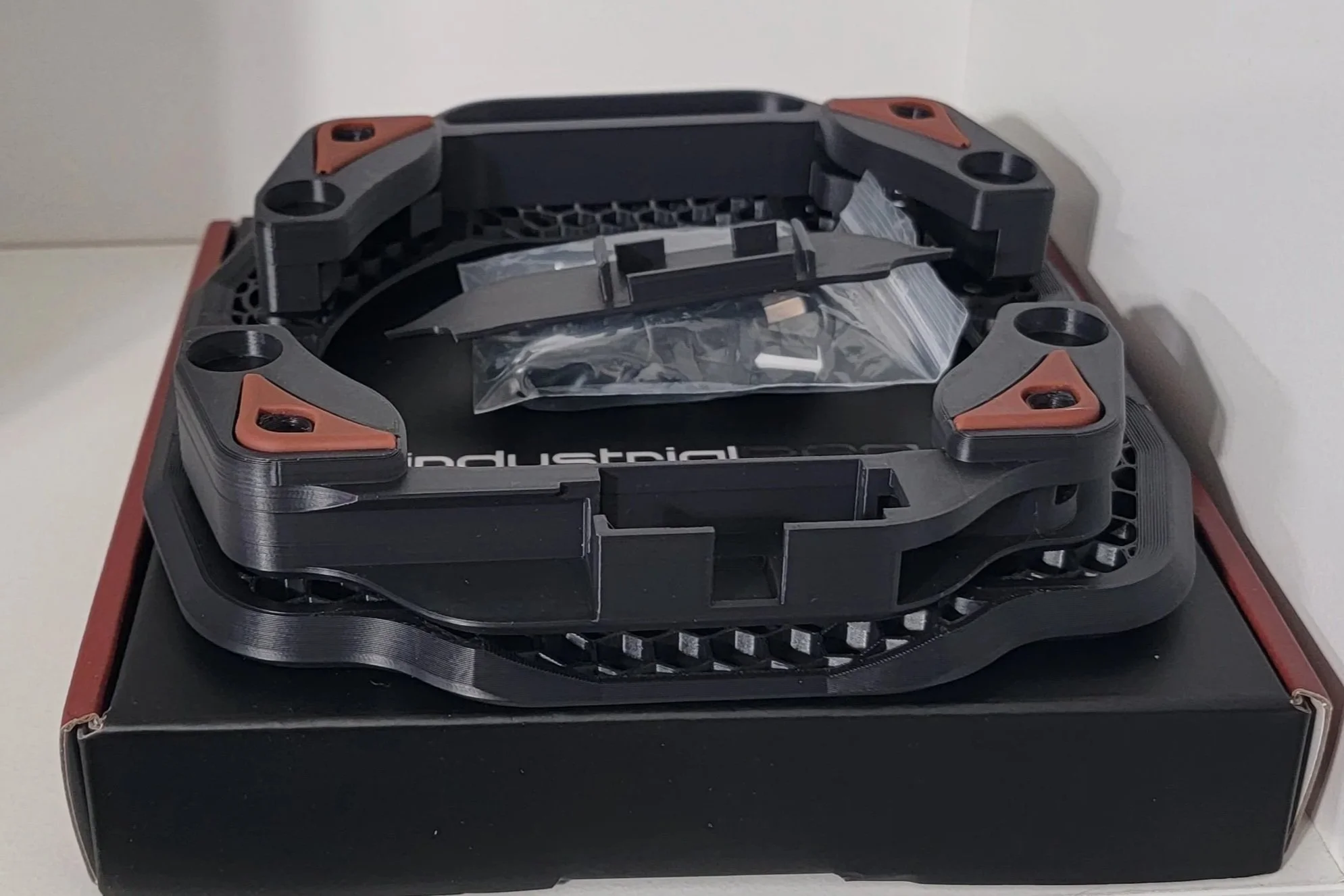
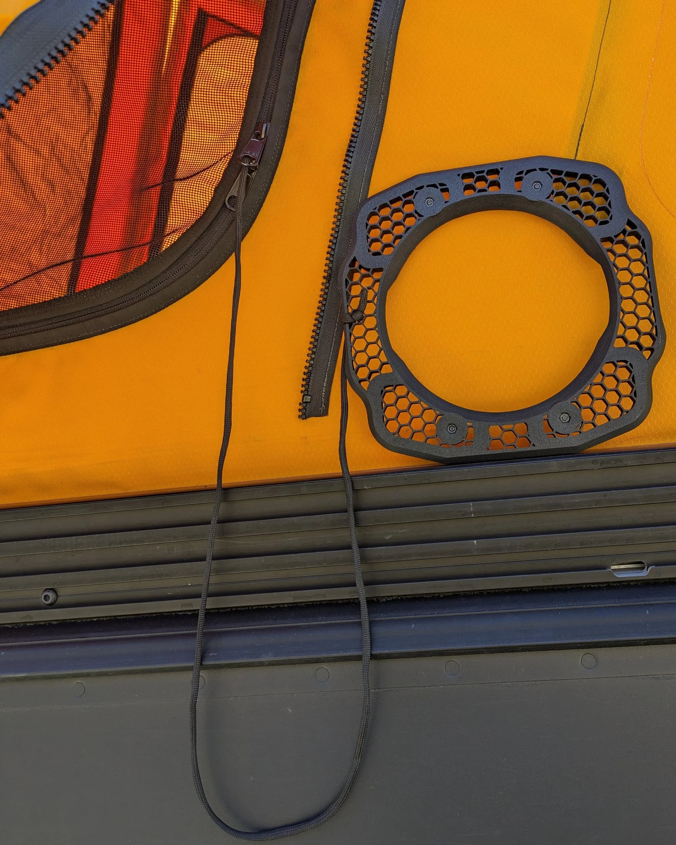
2. Magnet Mount Engineering
Magnets were selected as the mounting strategy to allow clean installation without permanent hardware.
The first version used sixteen embedded magnets rated at approximately 5 to 6 pounds each. While mechanically effective, sourcing magnets strong enough for embedding proved more expensive than using higher-strength surface-mounted magnets.
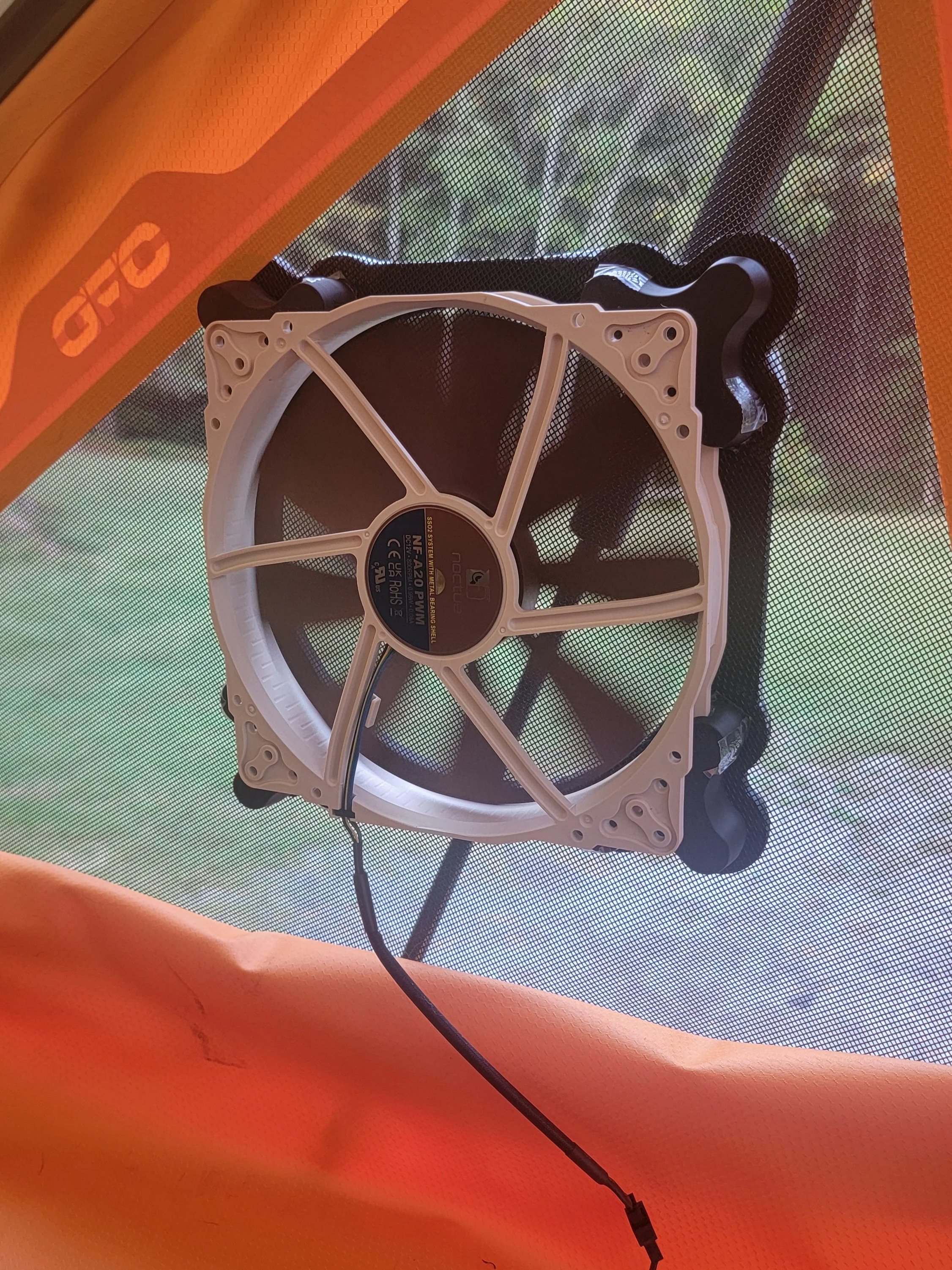
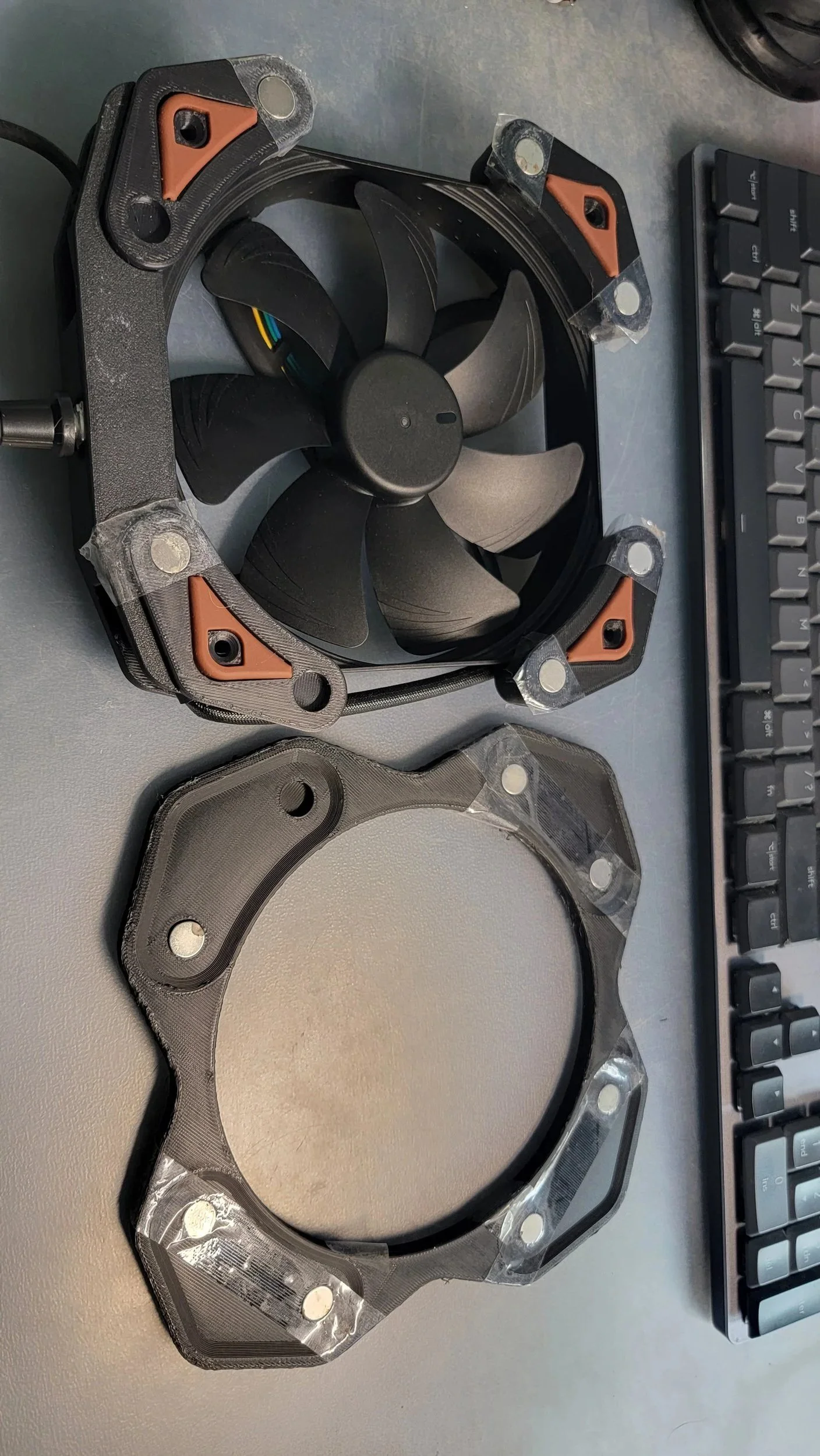
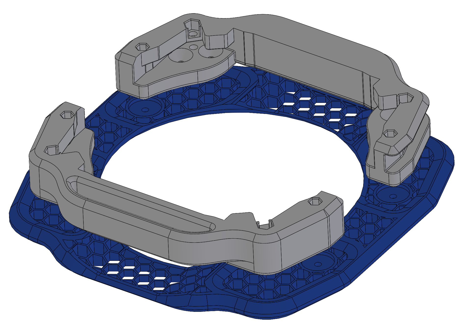
The design was revised to use four surface-mounted 20-pound magnets secured through a central fastener, paired with steel washers on the opposite side of the netting. This reduced cost, simplified assembly, and improved repeatability.
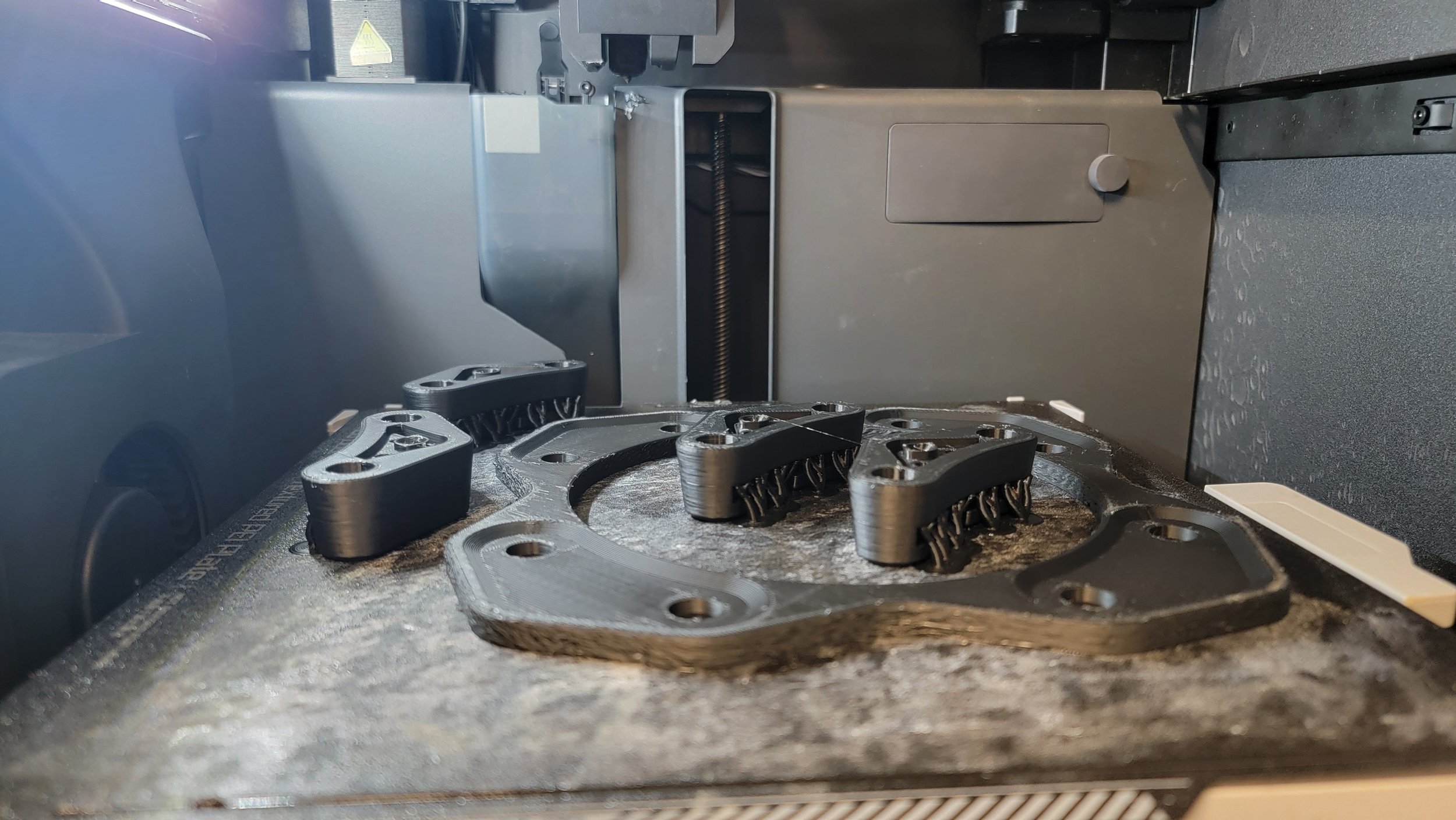
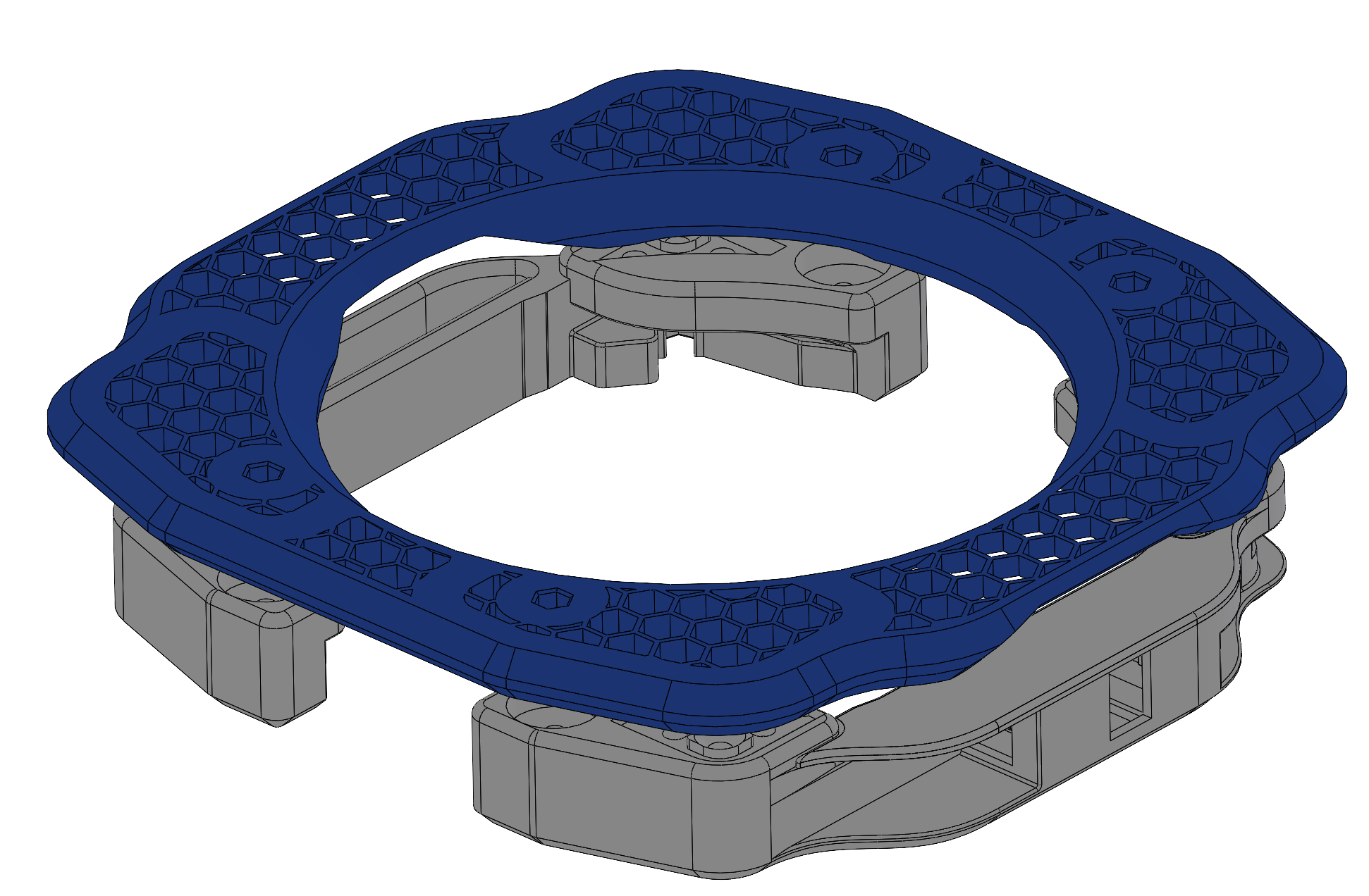
Early housing geometry consisted of four mirrored components positioned at each corner of the fan along with a solid backer plate. Through iteration, the design was simplified to a two-part system with an optimized cover plate. This reduced part count, improved print efficiency, streamlined assembly, and allowed the integration of a handle for easier positioning during installation.
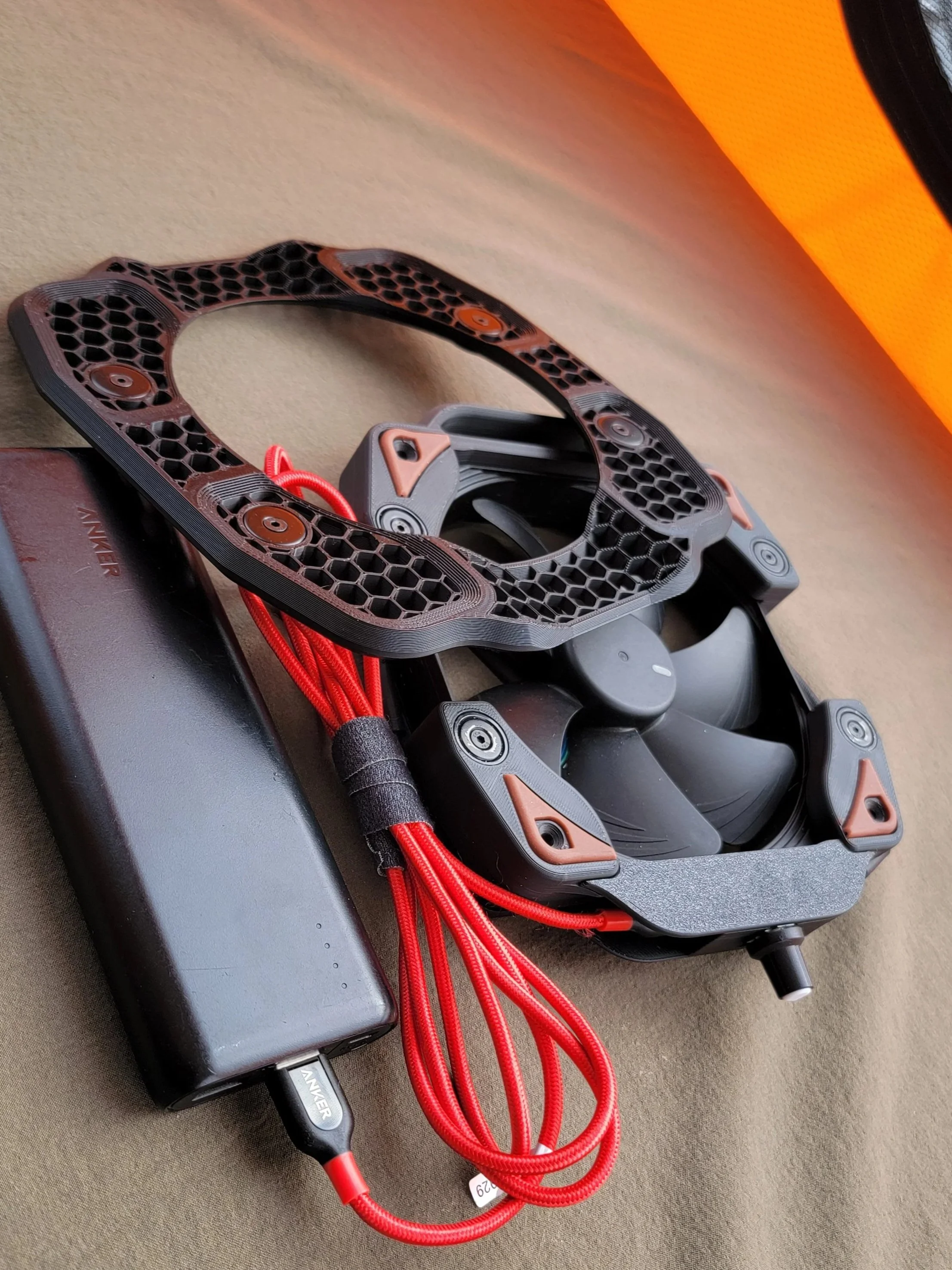
Because the magnets were intentionally overpowered for the application, the focus shifted from raw holding force to stability and fabric interaction. Silicone feet were added to increase friction against the netting surface and reduce sliding. Vibration-dampening pads, similar to those used in computer fan installations, were incorporated to minimize movement during operation.
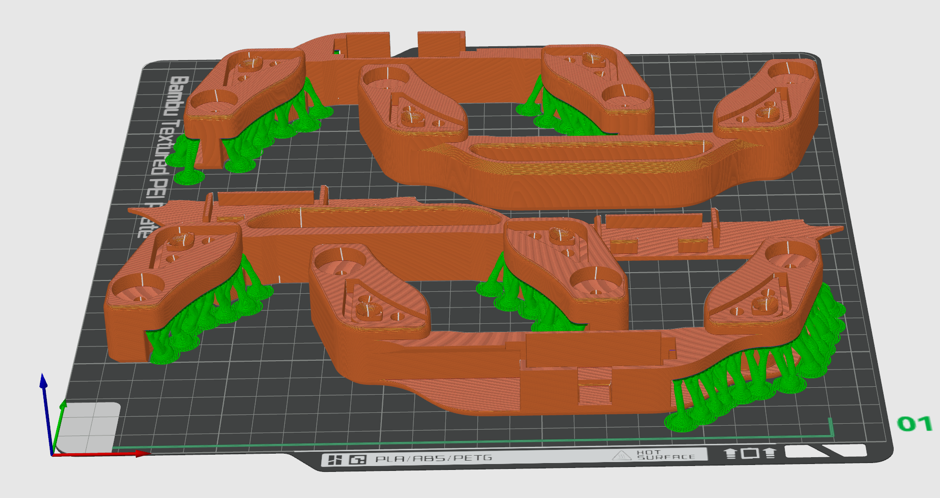
Approximately four iterations were completed before the final geometry was locked.
3. Housing and System Refinement
With mounting validated, the housing was refined to support the core requirements:
Structural reinforcement for durability
Compact packaging to reduce weight
Clean airflow path
Integrated speed control access
Cable routing and strain relief
Balancing airflow performance with quiet operation remained a key constraint throughout refinement.
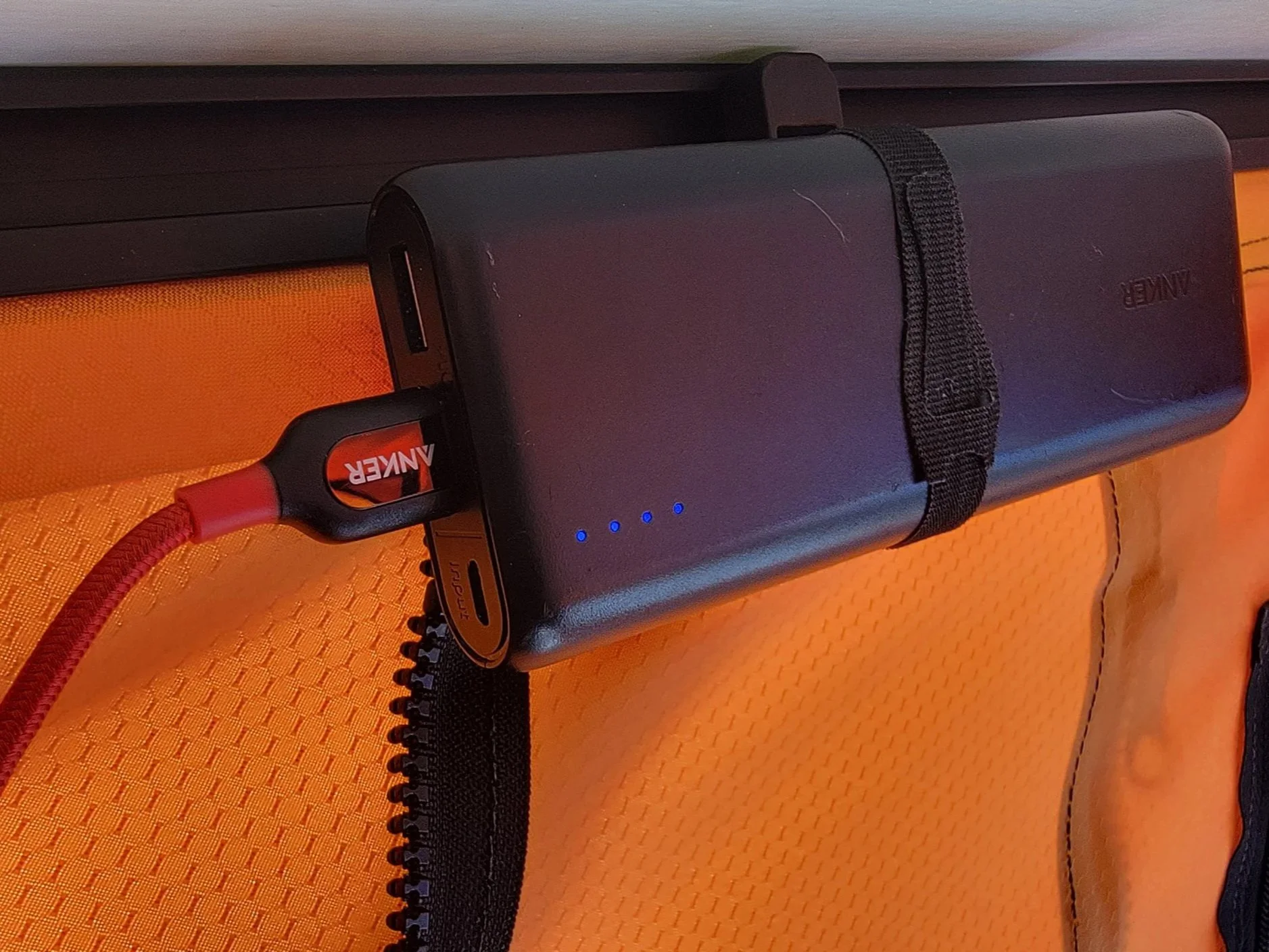
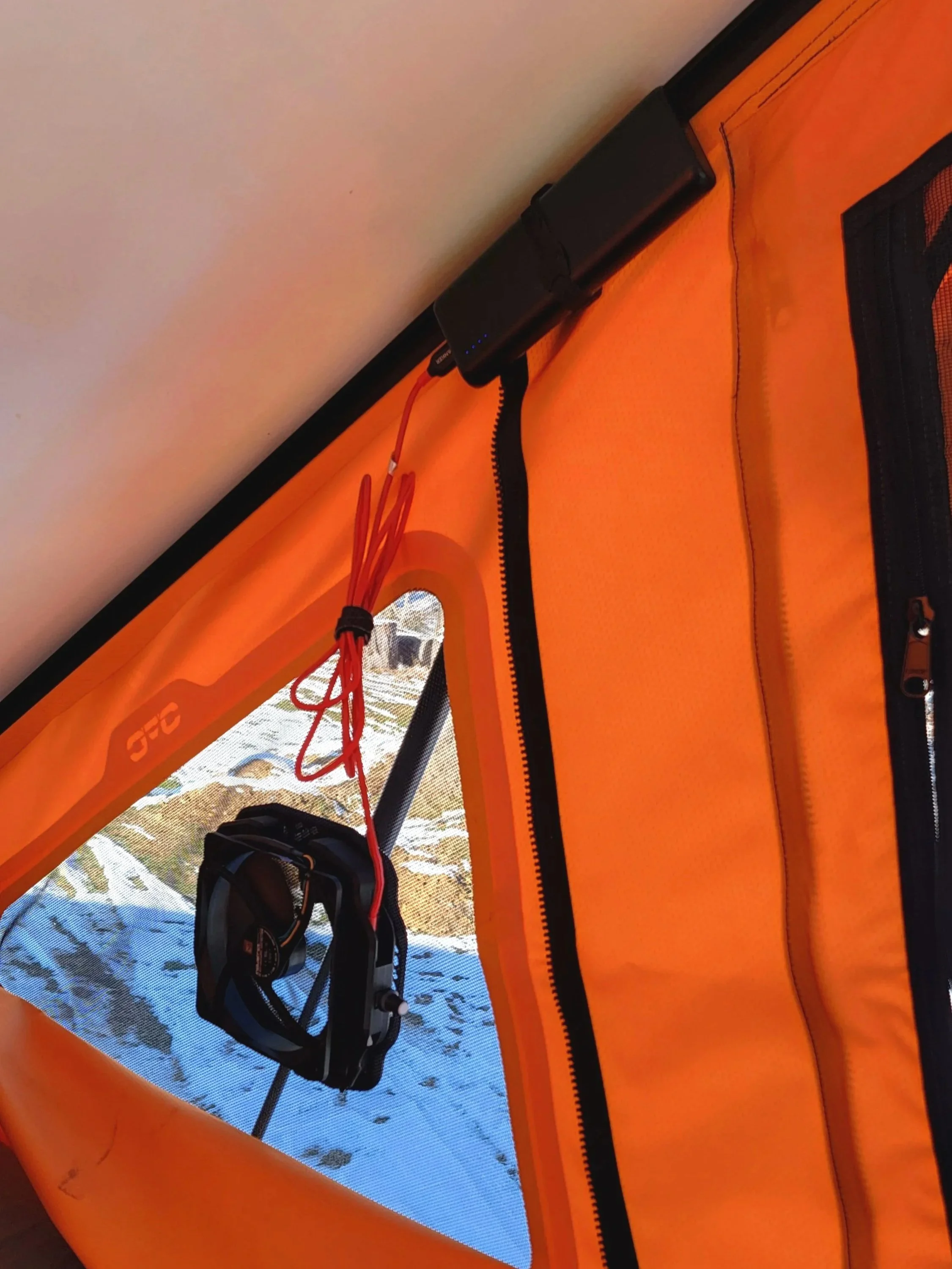
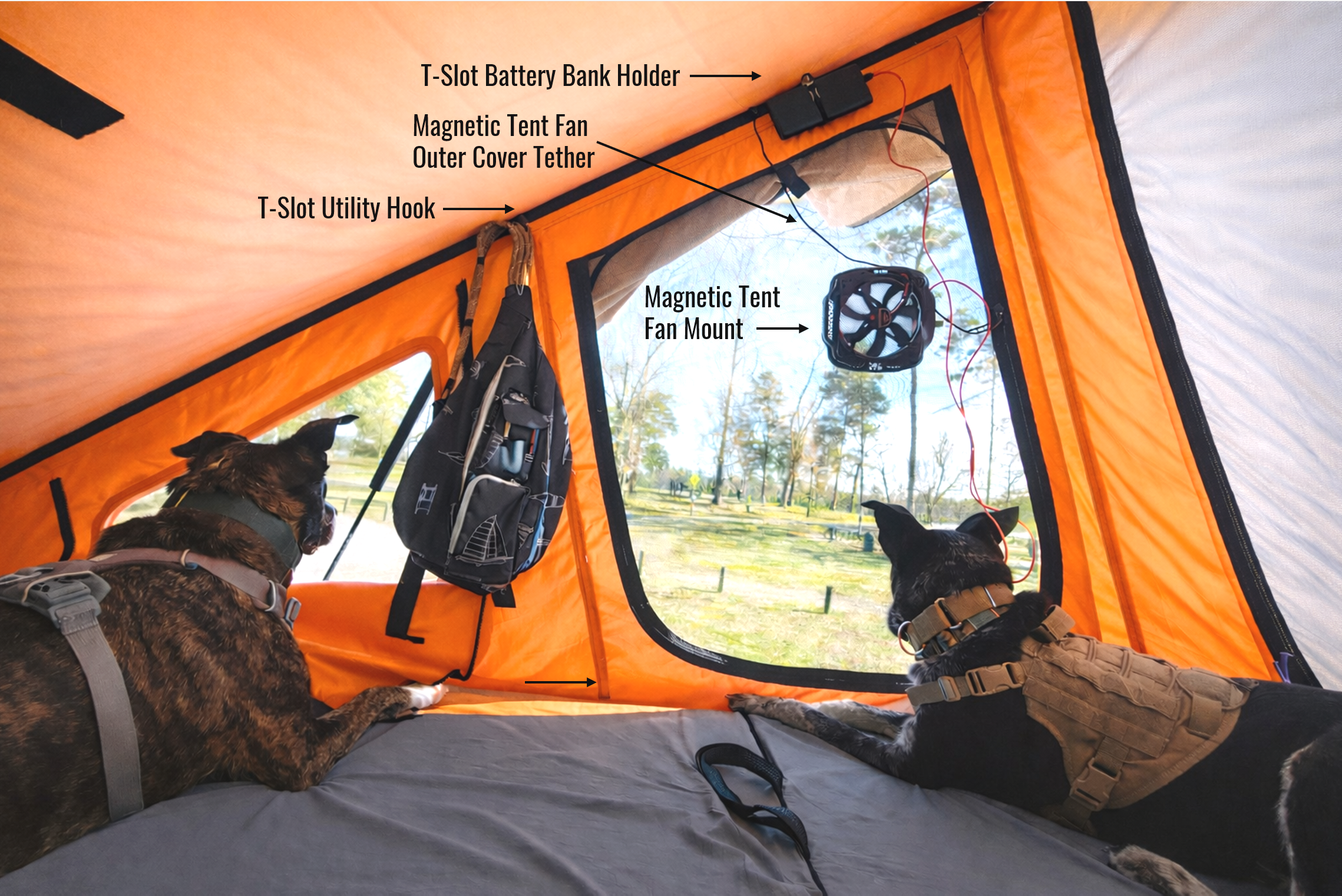
4. Power Integration and Ease of Use
Extended use highlighted the need for clean battery management and cable routing.
The system was designed to work with commonly available USB-C battery banks while keeping wiring simple and accessible. A dedicated mounting solution was developed to secure the battery along the tent frame, reducing clutter and improving ease of setup.
Adjustments focused on maintaining a lightweight, modular system without introducing unnecessary complexity.
Once the geometry stabilized, the focus shifted from iteration to repeatability.
This included:
Locking final design revisions
Standardizing print orientation and support strategy
Qualifying consistent production builds
Creating a complete bill of materials
Documenting assembly steps
Establishing basic quality checks
The goal was not just a working prototype, but a small-batch product that could be produced consistently
Production Development
Platform Expansion
With the core system stable, additional components were developed using the same structured approach:
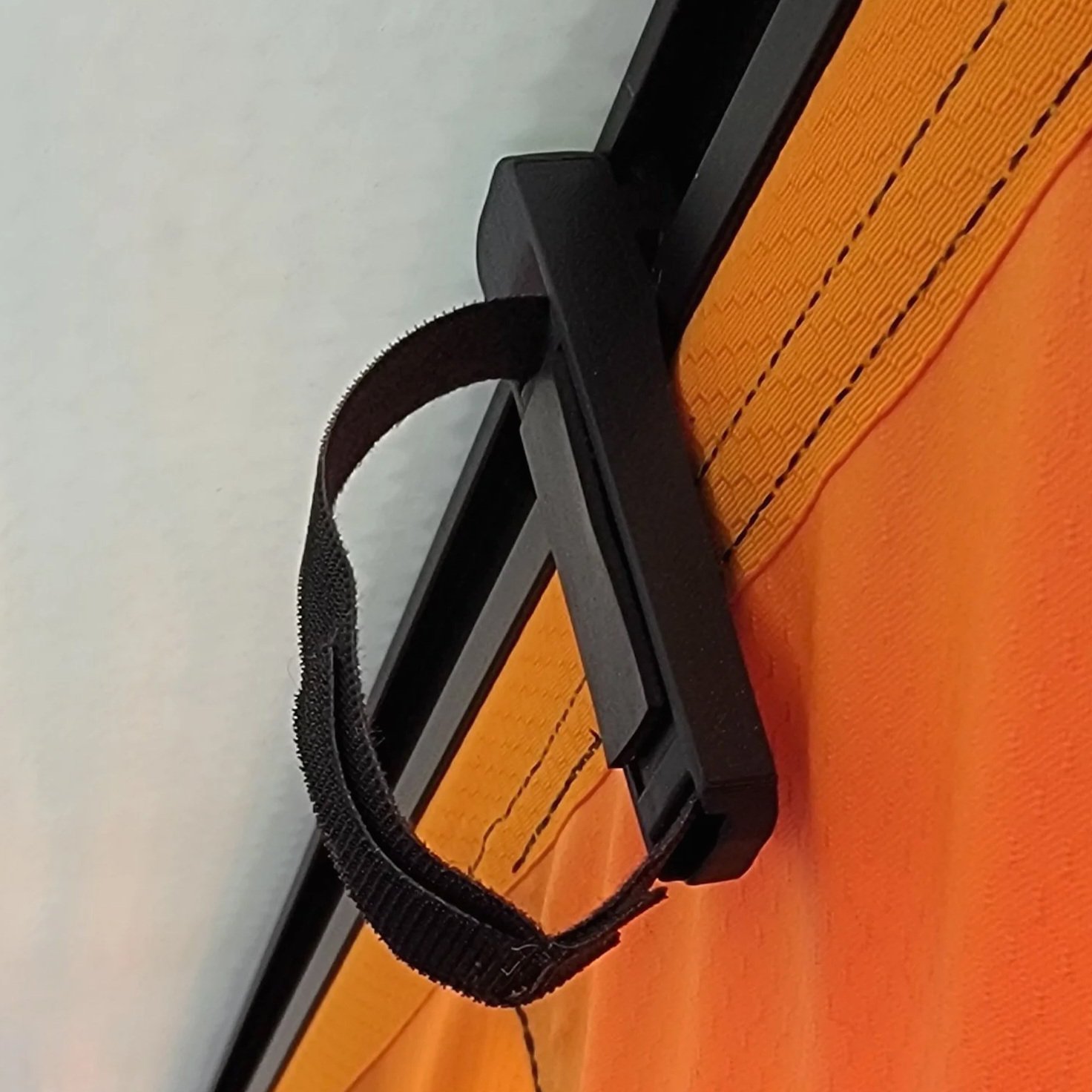
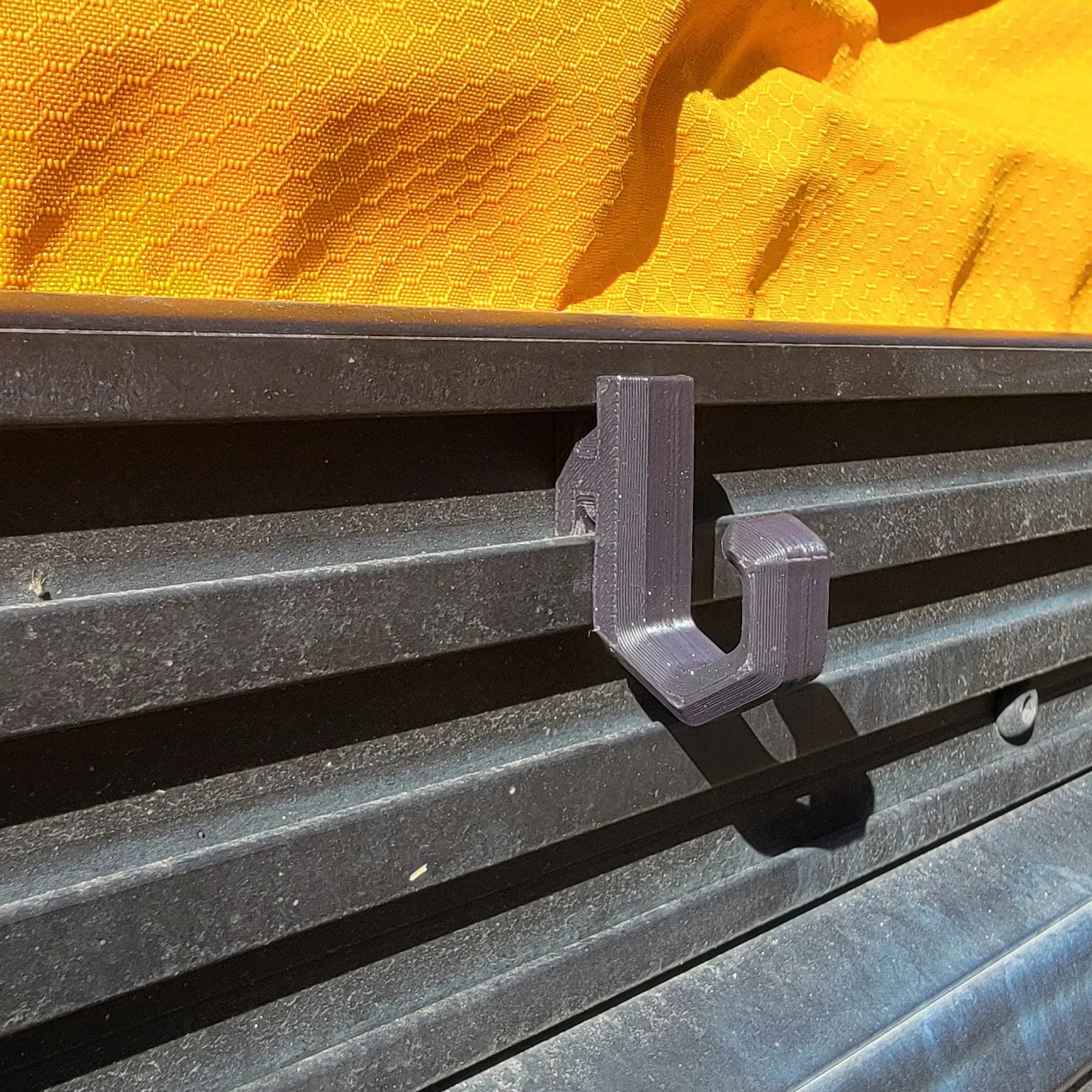
Utility hook variants
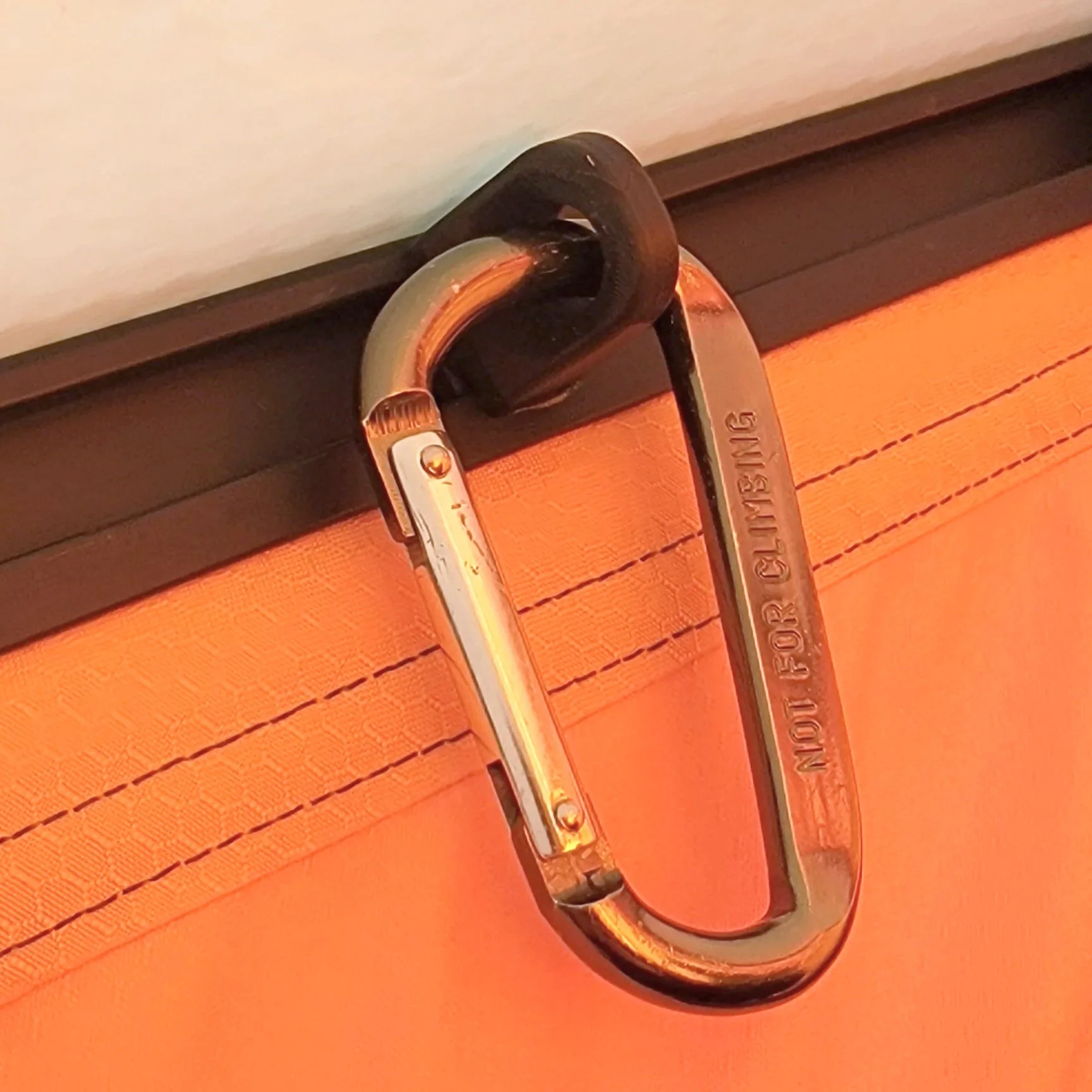
Carabiner-compatible mounts
Exterior tether system
Battery mounting options
Because the primary interface was clearly defined, expansion did not require redesign of the entire system.
Engineering Takeaways
Early comparative testing reduces downstream risk
Mounting constraints often drive more complexity than core function
Simplifying architecture improves cost and manufacturability
Additive manufacturing enables rapid refinement of constrained geometry
Production discipline separates a prototype from a product
Take the Next Step
If you have an idea and want to take it beyond a prototype, I can help you structure the development process and turn it into a reliable, manufacturable product.